|
|
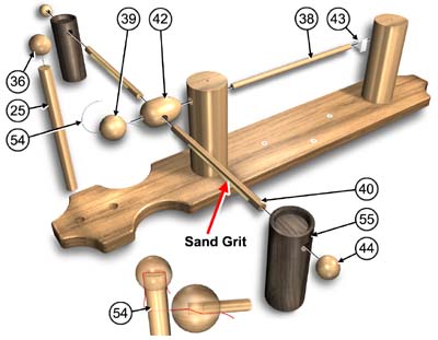
 PAGE 2. ESCAPEMENT SWING ARM
- Apply a small amount of glue along the top of both cross bars #6. (Do not get glue on ends)
- Sprinkle the fine sand grit (supplied) onto the glued surfaces.
- Press the swing shaft #38 into escapement pawl #43.
- Insert swing shaft #38 into the upper column #4.
- Slide swing bar egg #42 onto swing shaft #38.
(There should be about 1" of shaft left)
- Insert (2) cross bars #40 into the swing bar egg #42.
(Adjust egg till it is at 90 deg. to flat on pawl #43)
- Thread nylon line #54 through small hole in swing shaft knob #39.
|
|

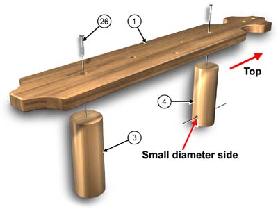
PAGE 2. BACK PLATE
- Attach lower column #3 to back plate #1 with screw #26.
- Attach upper column #4 to back plate #1 with screw #26.
(The smaller diameter cross hole must face down)
Use swing shaft #38 to align hole with back plate #1.
- Press swing shaft knob #39 onto swing shaft #38 trapping nylon line #54.
(Do not press all the way, adjust latter)
- Press the top shaft #25 into back plate #1.
(Hole must line up with swing shaft #38)
- Thread nylon line #54 through small hole in top shaft #25.
- Pull nylon line #54 over end of top shaft #25 and secure with knob #36.
(Swing shaft knob #39 should be about 1/8" from top shaft #25)
- Slide (2) weights #55 onto cross bars #40.
- Press (2) end knobs #44 onto cross bars #40.
|