

 Introduction
Stains & finishes
Parts List
 Page 1 Page 1
Page 2
Assembly
Page 1
Page 2 
Page 3
Page 4
Trouble Shooting


|
|
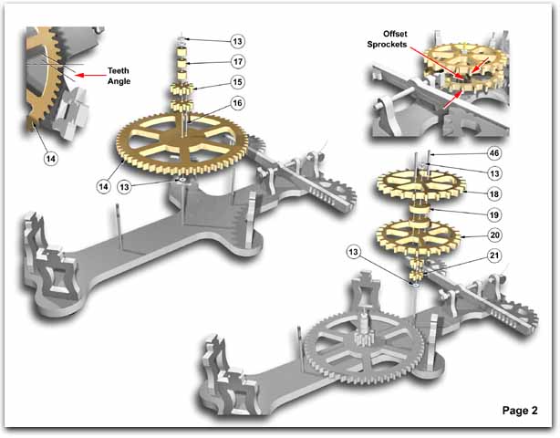
PAGE 2. MIDDLE SHAFT
- Assemble nylon washer #13 on brass shaft #11. (shaft #11 is plain and has no knurls).
- Gear #14 is next, the teeth must point in a clockwise direction.
- The 2 gears #15 are pinned together with a steel pin #16 (3/4" long). The teeth must
line up becoming one. If not, flip one upside down.
- Pin together with gear #14, (3) spacers #17 and (2) nylon washers #13.
- Temporarily load top plate #35 onto the (4) uprights #3. Carefully align brass shafts.
Check if gears rotate freely, then remove top plate.
PAGE 2. ESCAPEMENT SHAFT
- Assemble nylon washer #13 on brass shaft #10. (Knurled section on shaft #10 is
closest to backboard #1).
- Hold (2) gears #21 together with teeth aligned and slide them onto shaft. Press onto
knurl until they are against nylon washer #13.
- Lay sprocket #18 flat on the table. Insert (2) steel pins #46 (1 inch long).
- Slide (2) spacers #19 onto pins, followed by sprocket #20. The teeth on sprockets
#18 and #20 must be staggered. If not, flip the top one upside down.
- Load this assembly onto shaft #10 and push onto knurl against gears #21.
- Assemble (2) nylon washers #13.
- Temporarily load top plate #35 onto the (4) uprights #3. Carefully align brass shafts.
Check if gears rotate freely, then remove top plate.
|