

 Introduction
Stains & finishes
Parts List
 Page 1 Page 1
Page 2
Assembly
Page 1
Page 2
Page 3 
Page 4
Trouble Shooting


|
|
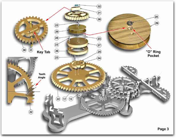
PAGE 3. BOTTOM SHAFT
- Place gear #22 flat on table with the teeth pointing in an anticlockwise direction.
- Place clutch cam #24 in the center. Make sure that the cam is pointing in the right
direction (see illustration).
- Lock together with steel pin #23 (1/2 inch long).
- Place (4) clutch dogs #25 around the clutch cam #24.
- Press rubber "O" ring #28 firmly into pulley #29 pocket.
- Remove brass shaft #12 from backboard #1.
- Place the pulley #29 with "O" ring side down, on table.
- Push the non-knurled end of shaft #12 into pulley #29 and through "O" ring.
- Push shaft #12 further through pulley, up to the knurled section. Make sure "O" ring is
still seated in pulley pocket.
- Slide clutch cap #27 onto shaft.
- Lock pulley and clutch cap together with (1) steel pin #23 (1/2 inch long).
- Attach clutch ring #26 to clutch cap #27 with (2) steel pins #23 (1/2 inch long).
- Place this assembly onto gear #22 over clutch cam #24 and clutch dogs #25.
- Assemble (1) spacer #17 and (2) nylon washers #13 onto bottom of shaft #12.
- Place assembly onto backboard #1.
- Push gear #30 onto shaft #12 against pulley #29.
- Insert key #31. Press into place.
The key is there to lock the gear #30 onto the shaft. If the key seems loose, turn it over
and file the tab to suit.
- Assemble washer #32 on brass shaft #12.
- Temporarily load top plate #35 onto the (4) uprights #3. Carefully align brass shafts.
Check if gear assemblies rotate freely, then remove top plate.
|