

 Introduction
Stains & finishes
Parts List
 Page 1 Page 1
Page 2
Assembly
Page 1
Page 2
Page 3
Page 4 
Trouble Shooting


|
|
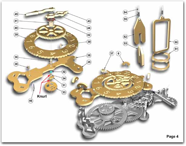
PAGE 4. FRONT PLATE ASSEMBLY
- Press bushing #36 and (3) wooden pins #38 into front plate #35.
- Press dial ring #39 onto front plate #35. Locate ring on top (2) pins then press bottom of
dial onto bottom pin.
- Insert shaft #34 into gear #33.
- Press key #31 into gear to lock onto shaft. If lock is not sufficient, turn key over and file
to suit.
- Assemble washer #32 on brass shaft #34.
- Insert assembly into bushing #36.
- Place gear #40 flat on table and press in bushing #41.
- Place washer #42 over bushing #41
- Press hour hand #43 onto bushing #41 (slip fit).
- Place gear #40 onto bushing #36.
- Place washer #44 onto shaft #34.
- Press minute hand #45 onto shaft #34. Do not press on all the way or gears will not turn.
- Press (2) steel pins #46 into the back of the front plate #35.
- Load top plate assembly onto the 4 uprights #3 and carefully align shafts and gears #30
and #33.
- Press gear #37 onto brass shaft #12. Check if all gears rotate freely.
- Lock top plate assembly onto (4) uprights #3 with keys #6. If gears run freely we can now
lower the swing shaft #8 by releasing wedge #47. The escapement pawl #7 should be
12 mm or 1/16" inside the sprocket wheels #18 and #20.
PAGE 4. PULL STRING ASSEMBLY
- Thread braided cord #54 through openning in lower clock frame, around pulley #29 and
back through lower frame.
- Cord should be retained by the (2) steel pins #46 on back of front plate #35.
- Slide (1) heat shrink tube #55 onto each end of cord.
- Thread left end of cord through weight frame #50 and right end of cord through counter
weight #52.
- Slide heat shrink tube #55 onto each end of cord and carefully hold next to candle flame
or heat gun until it shrinks onto cord. (DO NOT hold above flame).
- Place full pop can into weight frame #50 and slide (2) weight rings #51 onto weight
frame #50. (Lower ring should be about halfway up the frame).
- Slide counter weight fin #53 onto counter weight #52
- Remove wedge #47 and pull swing shaft #8 up high enough so that escapement pawl
#7 is about half way up the teeth of escapement sprockets #18 & 20.
- Replace wedge #47 making sure the string is positioned in the middle of the square hole.
A set of metal weights can be ordered separately. The large weight is 600 grams, and
the small weight (counter weight) is approximately 100 grams.
|